 |
|||||
|
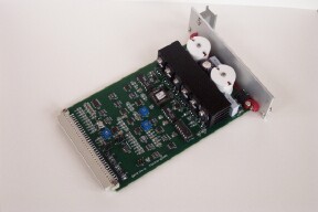
Description: The controller board is designed for closed loop control of a voicecoil actuator system that comprises a voice coil motor, position sensor and guide system. There are 3 sections to the board.
Specifications:
Sensor signal processor: In a typical application a spot of light from an LED
is incident upon a quad cell. The position information is contained
in the amplitude of the four signals from the quad cell. The processor
forces the sum of these four signals to equal a reference voltage,
which compensates for ageing of the LED and responsitivity of the
quad cell. Controller: The PID controller uses a 2nd order rate loop (gain and zero placement) enclosed within the position loop. Ki and Kd control the zero location and gain. Kp sets the position loop gain. It receives the position information from the sensor processor , and an external command position input. It generates the motor driver command signal which forces the sensor position to match the command position input. Driver: The power driver is a PWM driver operating at 100kHz. The output is filtered at ~15 kHz to remove most of the fundamental and almost all of the higher harmonics of the PWM frequency. The output is almost a pure replica of the command input with very little noise. The power rail is typically 24 volts, however rails up to 100 volts can be accomodated. Specifications: max current ± 2.6 Amps
|